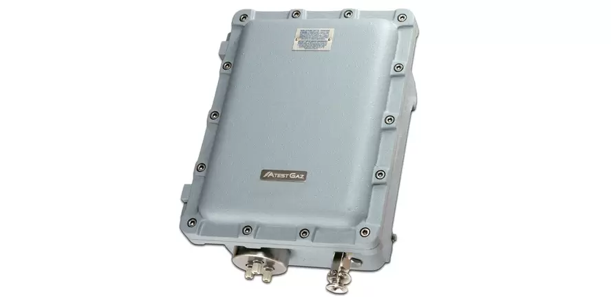
Sigma Control L control unit
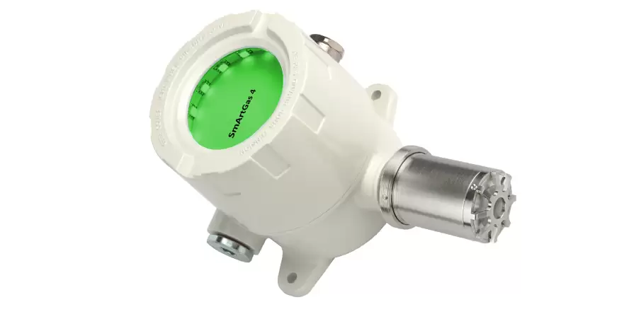
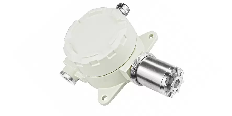
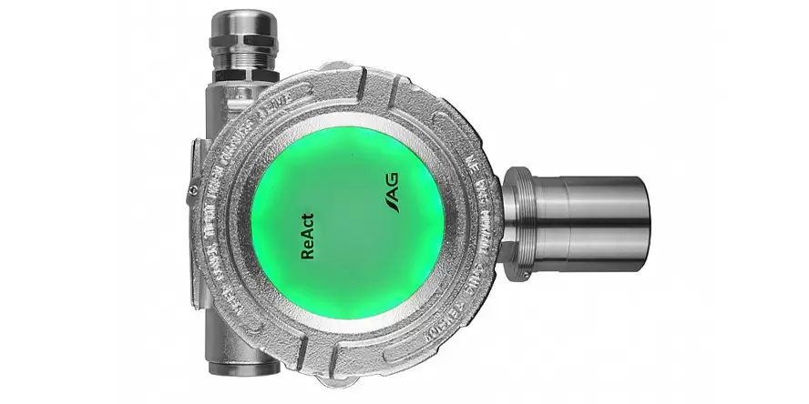
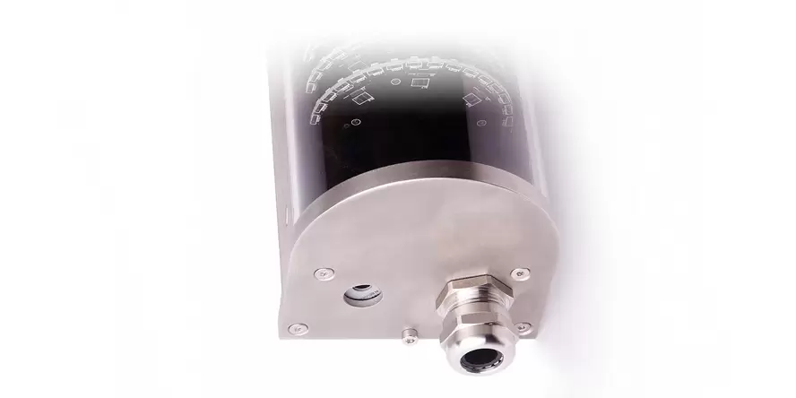
The Sigma Control L control unit supports between 1 and 20 sensors (depending on type) SmArtGas 4, ProGas 4 or ReAct 4. It is designed to indicate the conditions of the sensors connected to the system, and this information is presented on the display and on the built-in System Optical Indicator
Unique features
Immediate assessment of the security system “at a glance”
Supports 1 to 20 sensors
The Extension Module interface allows connectivity to DCS, SCADA, PLC or fire protection systems
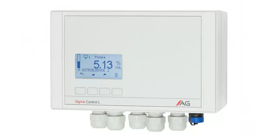
Based on the measured gas concentration and other special conditions (e.g. malfunctions), the Sigma Control L control unit controls the available outputs for the control of optical and sound signalling devices and two-state outputs
The Sigma Control L control unit reads:
- signals from the gas sensors connected to it (measured values, diagnostic information, etc.),
- signal from dual-state input,
- operator commands (keypad).
Based on this information, Sigma Control L:
- activates connected indication devices (sound and optical),
- generates optical and sound indications for users,
- activates output signals from the system (e.g. to the DCS or ventilation system).
Extremely simple assessment of the entire system “at a glance”
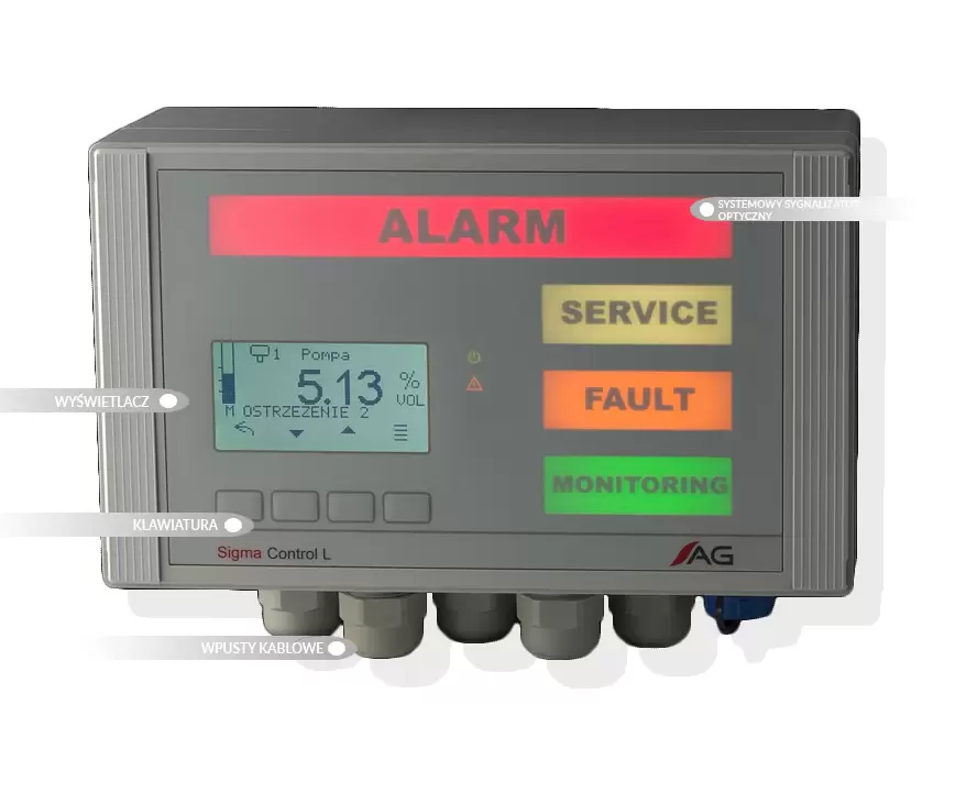
The System Optical Beacon, fitted to the Sigma Control L Unit, allows the operator, normally focused on other activities, to make quick assessments of the gas safety status of the facility – by glancing at this beacon and seeing that only the green light is on. The System Optical Beacon presents four independent indications:
The green “MONITORING” light is active if at least one of the connected sensors is measuring the gas concentration.
The yellow “FAULT” light is active if at least one of the system components included in the self-diagnosis is faulty.
The white “SERVICE” light is active when at least one of the system components is in a service state (e.g. annealing, calibration, “inhibit”, test or system configuration).
The red “ALARM” light is the largest and most important for assessing the status of the system. It is activated when at least one gas sensor detects a dangerous concentration.

Why choose the Sigma Control L control unit?
Support for 1 to 20 sensors.
Two 24 V DC outputs dedicated to controlling the optical and sound signalling device.
Three configurable two-state outputs that can perform the functions listed below:
- output signal activated when sensor warning and alarm thresholds are exceeded
(warning 1, warning 2 and alarm), - system status indication by means of a system optical alarm,
- pulse valve control,
- the possibility of negating or delaying the tripping of the outputs,
- the two-state input that can operate in different modes: as an external alarm or external fault (thus enabling easy integration with other systems, e.g. fire).
Modern, easy-to-use, intuitive and clear user interface.
Control of the Gas Safety System through commands:
- removal of the sensor lock (functionality available e.g. for sensors with a catalytic sensor – deactivates the lock protecting the catalytic sensor against overload),
- switching sensors into “inhibit” mode (allows temporary deactivation of selected gas sensors; a sensor switched into “inhibit” mode will be ignored by the System)
- changes to the sensor parameters, e.g. alarm thresholds, noise gate level, sensor sub-parameterisation,
- testing the output signals of the device, the user interface.
Event history – recording events related to system operation.
Security – two levels of access to change parameters, protected by passwords.
It has an expansion slot that allows modules to be added to extend the available functionality, such as:
- RS-485 output module for communication with DCS or SCADA,
- web-based visualisation of system operation – access via Ethernet
An internal sounder, known as a buzzer, is built into the Sigma Control L Control Unit Module. It generates sound in cases where operator intervention may be required, such as a gas hazard or failure of a part of the system. The buzzer is activated in the event of:
- gas alarms, i.e. the appearance of the first and second warning and the alarm reported by any of the connected sensors,
- failure, i.e. the occurrence of a critical failure of any of the connected sensors, a loss of communication with them and in the event of a critical failure of the Control Unit Module.
