Zbigniew Wolff | GRUPA WOLFF
Where the production process involves combustible dusts, gases, vapours, or hybrid mixtures, an ignition can occur in a device or apparatus and, in consequence, an explosion. Since process plants constitute a kind of set of connected vessels, an explosion can spread to subsequent devices. This phenomenon is unacceptable from the point of view of explosive safety, but also from the point of view of the Polish and European law. But how to counteract it effectively? Learn the advantages and disadvantages of commonly applied protective systems.
As a rule, industrial devices do not function as autonomous entities. Most of them are interconnected with other process apparatus through different types of conveying systems, pipelines and channels. When flammable and explosive dusts, gases, vapours, or hybrid mixtures take part in the process, there is a serious risk of ignition and explosion. Effects of an explosion in an apparatus, i.e. flame and pressure, may be transmitted from that apparatus to the process installation connected to it. This can occur even when the device is protected against the effects of explosion by an explosion relief (venting) or suppression system of the HRD type.
Due to the high probability of explosion propagation between individual apparatuses of the process plant endangered with an explosion, the ATEX 137 and 95 Directives, as well as the Polish regulations and standards, impose on the plant owners the obligation to apply certified explosion decoupling systems (also called explosion isolation systems or fire barriers).
Several solutions that meet the requirements of the ATEX directive 95 are available on the market. However, they not always can be applied interchangeably and some of them are dedicated exclusively for specific applications and solutions. Below, the most important types of explosion decoupling systems are presented.
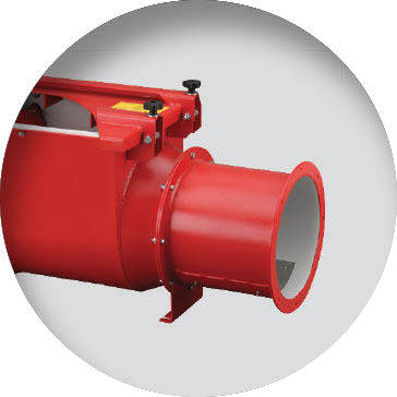
Back pressure flap
Back pressure flaps are an explosion isolation system dedicated to combustible dusts that are fan-extracted in vacuum dedusting units and/or central vacuum systems. The advantages of the solution are simple installation and a relatively low price.
Note, however, that due to the principle of operation, valves must be installed in a horizontal position and on a straight section of the pipeline (on the stretch between the flap and the device, no knees and other curvature can occur). Moreover, choosing a back pressure flap for a particular solution, the pressure drops generated by the flap should be taken into account. It is equally important that the diameter of the pipeline is the same size as the flap connections. One must also remember that a local change in the diameter of the pipeline, as aimed at adapting it to the dimensions of the back pressure flap, can have a negative impact on the proper functioning of the safeguard at the explosion time. In the event of an explosion, the flap must be most frequently returned to the manufacturer for inspection and re-admission to the operation.
Due to the principle of operation, internal elements of the flap valve are exposed to accelerated wear and in some cases, also to being coated with dust (moisture), which can lead to an abnormal operation of the system. For these reasons, back pressure flap s are subject to frequent inspections and surveys (inspections every 10-20 days on average; surveys on a quarterly basis and, where appropriate, even once a month). It should be remembered that the plant must be disabled during an inspection or survey.
It is very important that users of back pressure flaps are familiarised with the manufacturer’s documentation observe rigorously the recommendations contained therein. For example, in the Polish regulations, there is an outright requirement concerning surveys – they should be carried out in accordance with the manufacturer’s documentation, but not less frequently than once a year.
A significant limitation for the use of back pressure flaps results also from the maximum values of the dust explosiveness parameters Kst and Pmax for which they can be used. In most cases flap valves with a diameter of DN315 can be used for dusts of classes St1 and St2. Flap valves with larger diameters can only be applied for the class St1 dust. Please also note that the reduced explosion pressure Pred in the dust extraction unit may not exceed the value of 0.5 or 0.6 bar, depending on the diameter of the back pressure flap.
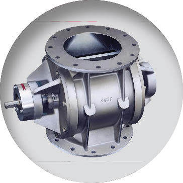
Rotary valve
Rotary valves are used as a dosing systems for feeding dry products and sluices to limit air flow in dust collection, central vacuum, and pneumatic conveying systems, etc. In addition, in the case when they are certified in accordance with the requirements of the ATEX 95 directive, they can be operated in the explosion risk zones and as the so called autonomous explosion decoupling systems.
Thus, depending on whether the rotary valve is certified to ATEX or to what extent a certification has been carried out, three types of devices can be named.
Rotary valves in the regular design that under no circumstances can be used in explosion risk areas and much less as decoupling systems.
Rotary valves with the ATEX certificate allowing for their operation in explosion risk areas, if properly selected, are not a source of ignition of a potentially explosive atmosphere. Neither can such type rotary valves be used as explosion decoupling systems.
Rotary valves with the ATEX certificate allowing for their operation both in explosion risk zones and as autonomous explosion decoupling systems (in the design resistant to a pressure and/or flame breakthrough).
When selecting rotary valves, the latter two types of the devices are often mistaken for each other. For instance, in requests for quotations and technical specifications, there frequently appear requirements that cellular wheel sluices must be ATEX-certified for a particular hazard zone – e.g. 20 inside and 22 outside the device. However, that fact is ignored that the device will also work as autonomous explosion decoupling system. In consequence, incorrectly selected sluices are purchased and installed. Their subsequent replacement is frequently difficult and costly. It is because the manufacturer of the equipment purchased either or does not have rotary valves with the required certificate in the offer or the capacity of a properly certified sluice of the same size is lower than the required (due to the limitations included in the certificate for decoupling of explosions).
Buying a larger device can be a way out of this stalemate. In this case, however, modifications to the installation – frequently expensive – must be reckoned with.
In some cases, application of an explosion decoupling system of the HRD type may prove to be a better solution than a replacement of the rotary valve. In most cases, this solution does not require an additional space for installation and the system can be installed directly on the existing channel or dump station (downstream the flap valve).
Just like any other anti-explosive system, rotary valves with the ATEX certification also require regular servicing. In this case, however, the producers most frequently indicate maximum periods between the subsequent overhauls in the technical documentation, with a reservation that an exact frequency depends on operating conditions and should be determined by the plant operator based on the operational experience.
In practice, this means that the services must be, in some cases, carried out several times a year or else, the ATEX certification will become invalid (certificate is valid for the maximum permitted gap between the rotor blades and the valve body).
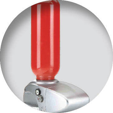
HRD isolation system
The type HRD isolation system is the least invasive, and at the same time the easiest to use anti-explosive system intended for both newly constructed and existing plants. The basic elements of the system are: HRD cylinders with explosion suppressant powder, dynamic pressure sensors and/or flame sensors and a control unit.
The solution based on HRD cylinders can be used in most industrial installations, where we have to deal with dust, gases or hybrid mixtures, and with a closed-circuit transport (pipelines, canals, gravity, chain, scraper, or pneumatic transport systems, closed conveyors, etc.), as well as in all types of dedusting and central vacuum systems.
For the most advanced HRD systems on the market, restrictions on the use of the system are very limited and related to some specific and rare circumstances. We are talking here about the restriction resulting from the maximum limit values of the following coefficients: Kst (up to 500 bar x m/s), Pmax (12 bar), Pred (2 bar) and the presence of group IIC gases or metal dusts in the process. However, such situations are so exceptional that their market share can be counted in parts per thousand.
Both restrictions and requirements for installing HRD systems of individual producers are entered in ATEX certificates. To avoid any “surprises”, before choosing a system, the restrictions recorded in the certificates must analysed in detail and compare them with the design input or conditions prevailing in the operating system. This is especially important because the admissions and restrictions on the application of systems of individual manufacturers differ fundamentally.
Explosion isolation systems based on the HDR technology are also subject to mandatory inspections and their complexity and time requirements differ, depending on the manufacturer of the system. For the most advanced systems, inspections should be conducted once a year. There are also commercially available systems which require up to four inspection a year. So the high frequency of inspections (and the resulting costs) can quickly even out the apparent savings resulting from lower cost of the system.
In case of systems of some manufacturers, another problem may be the need to relieve the pressure in HRD cylinders or to lock them mechanically (it is easy to forget it before restarting) for each operation related to servicing of the process plant. Since any such operation requires a shutdown of the plant, prior to selection of the explosion insulation system, it should be established how frequent downtimes are acceptable to the user.
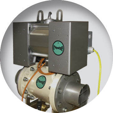
Quench valve
This solution is a rather rarely used because of its price, nonetheless, it has two unique features. The first one is the option to activate the valve by a signal from the decompression panel (explosion relief system) or an individual infrared sensor and the other, the possibility of reusing it after activation.
Since the main element of the valve member is a rubber sleeve which is clamped under pressure (min. 6 bar at the compressed air installation), its activation delay is significant as compared to e.g. the HRD system. As a result, the quench valve has to be installed in a considerable distance from the protected apparatus.
Due to its construction, the valve may only be used at pneumatic conveying lines or circular channels of dedusting systems. The respective admissible dust explosiveness parameters are as follows: Kst up to 200 bar×m/s, Pmax up to 10 bar and Pred up to 1 bar. Note, however, that the service life of the rubber contributions can be significantly reduced in the case of the products causing abrasion and with the increase in the flow rate of the product. Although the interval between inspections is one year, in the case of difficult media (abrasion), one should consider shortening of the interval to 2 or 3 months, since the probability that a worn-out valve will not close or will be too weak to stop the explosion is high in such a case.
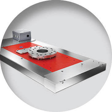
Fast acting valve
A fast acting valve is the most resistant explosion decoupling system as adapted to most difficult situations. It works like typical knife gate valves, with the difference that their reaction time and the closure is extremely short. Furthermore, their resistance to explosion pressure in the case of small diameters is as high as 50 bar (for larger diameters – up to 30 bar). These are the values that can probably be achieved only in the event of an explosion of hybrid mixtures. In standard applications, fast acting valves work with both dusts and gases as well as with hybrid mixtures. Just as HRD systems, they are activated by dynamic pressure sensors and/or flame sensors, and the whole system is managed by a dedicated control unit.
Fast acting valves can be operated a certified system of explosion decoupling at the plants which have been designed in such a way as to withstand the maximum explosion pressure (the so called structures resistant to 10 bar). The list of devices where this type of solution can be applied is virtually limited only by the diameter of the channel – it should not exceed DN400. We are talking here about filtration units, cyclones, reactors, dryers, pressure vessels, silos, mills, etc. The only drawback of this solution is a very high price, especially for larger diameters. In exchange, however, we get a system which after an explosion, we can activate by ourselves, without interference of an external service. This is essential for the plants where the time for restoring the system efficiency is crucial.
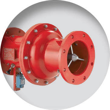
Ventex valve
VENTEX type valves are a passive explosion insulation system available in many sizes and versions. It is installed on channels of dedusting, central vacuum, positive and negative pressure transportation, drying or granulation systems. In most cases, these are structures resistant to maximum explosion pressures. The valve closes by the action of the explosion pressure wave moving in a pipeline. Due to the special design of the valve, in the form of a “pear”, the valve only slightly affects the mixture flowing through its interior. This solution is approved for use with flammable and explosive gases, dusts and hybrid mixtures. One must remember, however, that when dust are in the stream, their content must not exceed the limits specified in the documentation. This results from the valve structure, where the “pear” at the closure is pressed onto a special seal. Tolerances here are very small and amount to 0.1-0.15 mm. Too high dust content may cause overgrowing or abrasion of the valve seal, which may lead to malfunction.
Ventex valve is characterized by the widest range of versions. For example, it is available in a wide range of diameters (from DN100 to DN50), can be mounted horizontally or vertically, and provide single or bi-directional operation. Moreover, the available versions are made of stainless or normal steel and have an active closing mechanism.
The solution is simple to service and overhauls are usually performed not more frequently than once a year. Problems can arise, however, when there is too large amount of dust in the flow. A valve with a broken seal must be returned to the manufacturer for replacement and fitting of a new sealing. Since special equipment is needed, it is not possible to replace the seal on site. This involves about a month downtime of the plant or an installation of a reserve Ventex valve.
Summary
The basic objectives of the article were to draw attention to the need to apply explosion isolation systems and to identify the advantages and disadvantages of the different solutions available on the market. Although the material presented allows a broad look at the basic solutions, the selection the right system should be preceded by a study prepared by an engineer experienced in the field and by necessary calculations. Only such an approach ensures that an optimum solution is selected in terms of technology and economy, and, above all, in terms of process and explosive safety.
In order to facilitate the process of adapting production plants to the explosive safety requirements, GRUPA WOLFF has developed its own DSBW (Dedicated Explosive Safety System) programme. Its task boils down to analysing efficiently the critical components of the constructed or existing process plant and taking steps that will make it possible to eliminate them. DSBW is focused at the same time on three key areas:
- protection through identification and assessment of risks,
- protection through explosion risk assessment,
- protection through limiting the effects of an explosion to a level that is safe for working people and the environment.
The right approach to the problem of explosion decoupling will ensure that the system installed does the job and thus protects the personnel’s lives and health and the process installations.
