Interview
Wiesław Lehnhardt | Dalkia Poznań ZEC
Sebastian Słaboszewski | s.slaboszewski@grupa-wolff.com
Optical fibre temperature measurement technology is often used to measure the temperature of conveyor belt elements as long as several kilometres, fire detection, monitoring of power cables, the temperature distribution in buildings, leaks in dams, flood banks, etc. Today, we are presenting an interview with those directly involved in the deployment of that system in Dalkia Poznań ZEC.
Wiesław Lehnhardt (Dalkia Poznań ZEC), and Sebastian Słaboszewski (WOLFF GROUP) talk about the project background, potential risks in its completion, and the configuration of the implemented system.

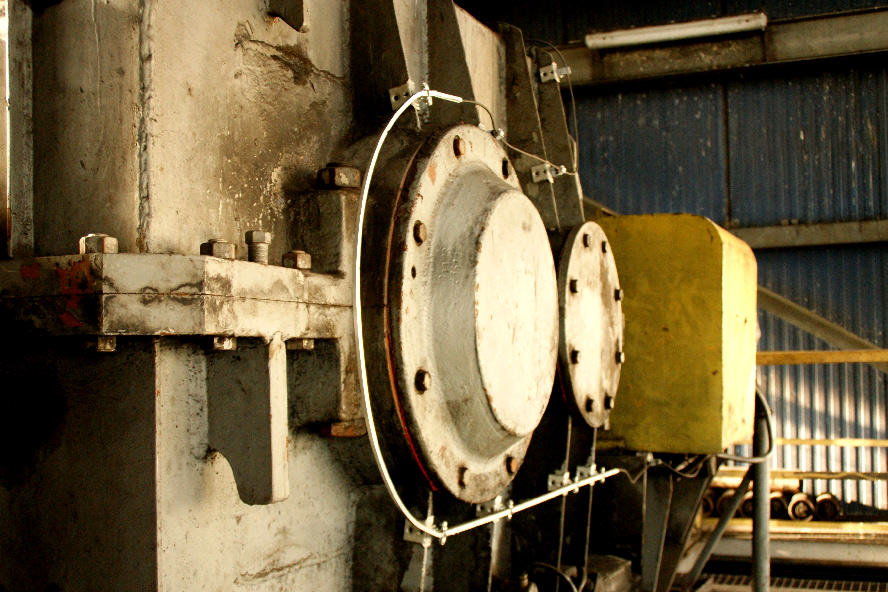
Photo. 1. Protection of conveyor drive gears with an optical fibre detector

Photo. 2. Return station protection
What are the origins of the project to install temperature detectors on belt conveyors at Dalkia Poznań ZEC?
Wiesław Lehnhardt Dalkia Poznań ZEC: For some time now, we have been implementing a long-term project for safety improvement on the power equipment in Karolin CHP Plant. A part of this project was to install a linear heat detector on the main belt conveyors PVII- 1, PVII-1,PIX-1 and PIX-2. These inclined bridge conveyors are critical to the CHP plant operations.
In February, works began at the Poznań Combined Heat and Power Plant to deploy a temperature monitoring system for bearings and belt conveyor rollers. The key objective of the system, based on an optical fibre linear heat detector, is to protect the coal dust handling system from fire and explosion of the dust-air mixture. At the same time, the system is used for continuous monitoring of the equipment health, including gears and bearings of the drive, divert and return drums. This reduces the system running cost.
Let me ask Mr. Sebastian Słaboszewski, who coordinated the delivery of the system, to describe to our readers the situation at the project site.
Sebastian Słaboszewski: The works were performed on two conveyor belt lanes located on inclined bridges. Each of the lanes included two conveyors, the shorter one is 80 m in length, and the longer measures 200 m. The total length of the conveyors was thus well over half a kilometre.
All works were performed in a running plant, which required precise timing of the relevant activities. On the one hand, the works had to stick to the schedule and, on the other, continuity of production and work safety had to be taken into account.
Which stage of the work was crucial to the success of the project?
S.S.: There were only 4 weeks to complete the task. At that time, almost 3,000 m of optical cable, to form a loop around all four conveyors, had to be routed. As a rule, the loop should consist of as few optical cable sections as possible, joined by splicing. In this particular case, the loop consists of 6 sections, with the longest being 900 m long.
At that stage, a thorough situation analysis was particularly important. All the critical components of the conveyors had to be taken into account. Based on the analysis, the optimum length of each optical cable section was determined.
You mentioned that one of the critical components of a conveyor is the belt tensioning system. What is so unique about that component and were there any other parts requiring special actions?
S.S.: The system consists of, among other things, a movable drum for tensioning the conveyor belt, which, in the case of a properly configured measuring system, may not be overlooked. The drum is “suspended” and changes its position in the vertical plane while the conveyor is running. The measuring cable should be placed in such a manner that it is not broken by the moving drum while being close enough to enable temperature measurements without any issues.
Rollers mounted on dynamic beams, which change their position angle, pose a challenge of a similar nature. The standard cable fixing had to be modified to eliminate the risk of damaging its sheath.
Another complication turned out to be the metal detection and separation system. Since the optical cable is reinforced with a steel braid and metal sheath, there was a risk that the strong magnetic field coming from the separator would pull it out of its fixtures. For that reason, the cable had to be properly secured and cleverly guided past the metal separators to eliminate failures during operation.
Please tell us how the linear temperature measurement system affects the daily use of the conveyors?
S.S.: The cable was guided so as not to interfere with the normal conveyor operation and to enable disassembly of the individual or an entire set of rollers, e.g. for vulcanisation of the belt. Furthermore, individual conveyor sections were provided with a surplus optical cable that can be used in case of unforeseen failures. An equally important issue was how to properly fix the cable in places where cleaning work is frequently performed. The solutions adopted had to be extremely durable and, at the same time, highly visible.
How the system was configured and what the criteria for activating individual alarms are?
S.S.: The system launched on the premises of Dalkia Poznań ZEC is intended to detect fire hazards occurring during the operation of belt conveyors, e.g. as a result of a failure of rollers or drive drums, and to prevent a possible explosion of the dust-air mixture. Through continuous measurement of temperature, the system indicates with an accuracy of 1 m, any irregularities that may indicate an emerging hazard, as well as the technical condition of individual conveyor parts. Then, depending on the detected threat, alarms defined according to the following criteria are triggered (the values given are initial, and each system is calibrated individually):
Maximum temperature alarm:
- Pre-alarm when local temperature exceeds 55°C
- Fire alarm for local temperature rise above 65°C
Differential temperature alert:
- Pre-alarm at local temperature rise above 15°C within 30 seconds
- Fire alarm at a local temperature rise above 25°C within 30 seconds
Adaptive maximum temperature alarm:
- Pre-alarm when the local temperature exceeds the average temperature measured in the control zone by 15°C.
- Fire alarm when the local temperature exceeds the average measured temperature in the control zone by 25°C.
Ice alarm:
- Ice alarm when the temperature drops below 0°C
On behalf of the editorial team, I would like to thank all the interviewees for their time and exhaustive description of the project. At the same time, I wish you further successful projects.

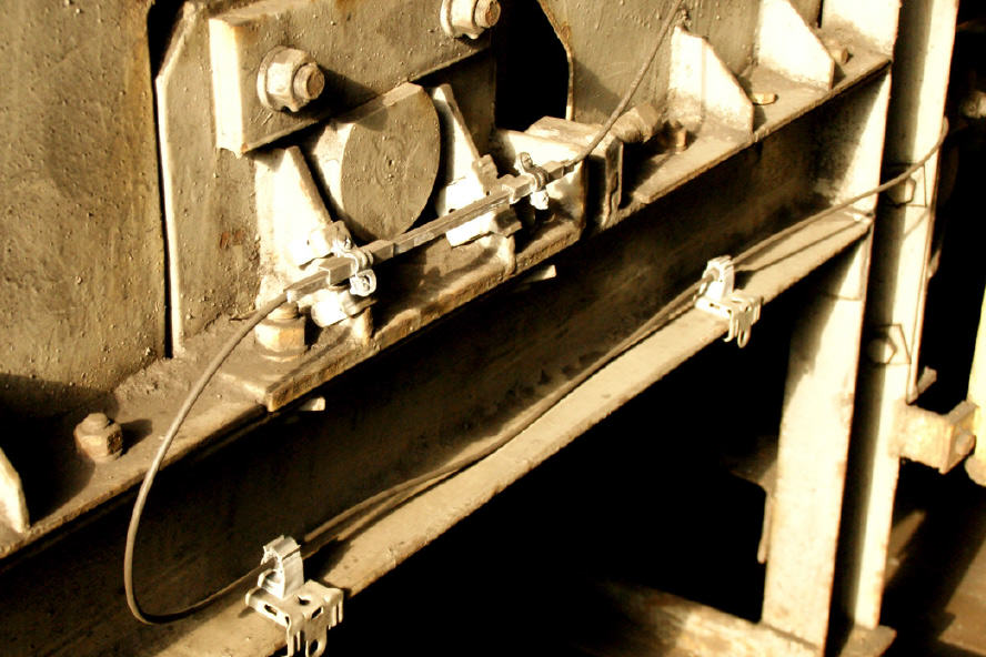
Photo. 3. Protection of the upper set of rollers with an optical fibre sensor

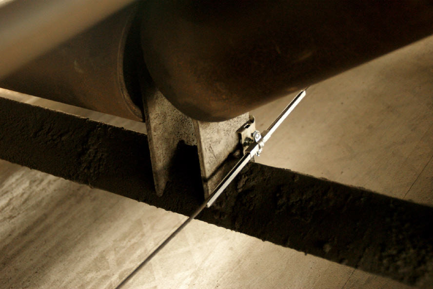
Photo. 4. Visualisation of the system for roller temperature monitoring


